0939 900 600
info@ldh.com.vn


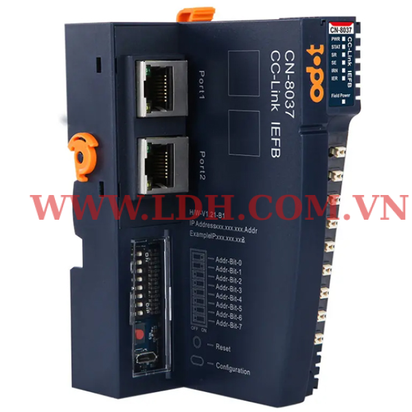
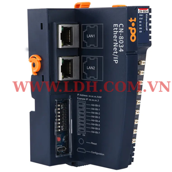
CN-8037 Bộ RTU chuẩn truyền thông CC-Link IEFB của ODOT
CN-8037 CC-Link IE Field Network Basic Network Adapter supports standard CC-Link IE Field Network Basic communication and remote equipment stations which could up to 16 stations at most. Its maximum transmission distance could be 100m. The maximum RX/RY capacity is 1024 bits, and the RWr/RWw capacity is up to 512 characters. Ethernet supports the cascade function of dual-port switches, with a communication rate of 100Mbps. The number of stations can be automatically calculated according to the number of IO modules in actual configuration, and the communication status of IO modules can be monitored in real time.
CN-8037 Bộ RTU chuẩn truyền thông CC-Link IEFB của ODOT
Technical Parameters
| Hardware Parameters | |
| System Power | Nominal:24VDC, Range: 19.2~28.8VDC Current: Max.2A@24VDC Protection: Reverse Protection, Overcurrent Protection |
| Module Power Consumption | 60mA@24VDC |
| Internal Bus Supply Current | Max.: 2.5A@5VDC |
| Isolation | System power to field power is isolated The field power supply is isolated from the system power supply at AC 500V The field power supply is isolated from PE at AC 500V The system power supply is isolated from PE at AC 500V |
| Power Supply | Power supply: 19.2~28.8V (24VDC nominal) Protection: Reverse Protection |
| Field Power Current | Max. DC 8A |
| I/O Modules Supported | 32 pcs |
| Wiring | Max.: AWG 18 Min.: AWG 24 |
| Installation | 35mm DIN-Rail |
| Size | 115*51.5*75mm |
| Weight | 130g |
| Vibration Resistance | Comply with IEC 61131-2 and IEC 60068-2-6 |
| Impact Resistance | Comply with IEC 61131-2 and IEC 60068-2-27 |
| EMC Performance | Comply with IEC 61131-2 and IEC 61000-4 |
| Environmental Parameters | |
| Operating Temperature of Vertical Installation | -35℃~70℃ |
| Operating Temperature of Horizontal Installation | -35℃~60℃ |
| Relative Humidity | 5~ 95%RH (No Condensation) |
| Storage Temperature | -40℃~85℃ |
| Storage Humidity | 5~ 95%RH (No Condensation) |
| Manufacturing Test Temperature | -40℃~75℃ |
| Ingress Protection Rating | IP20 |
| CC-Link IE FIELD BASIC Parameters | |
| Protocol | CC-Link IE FIELD BASIC |
| Station Type | Remote equipment station |
| Number of Logical Stations Occupied | 1~16(1 station has 64 bits RY data, 32 words RWw data, 64 bits RX data, and 32 words RWr data) |
| I/O Data Capacity | Maximum number of cyclic RY data: 128 bytes (1024 bits) Maximum number of cyclic RX data: 128 bytes (1024 bits) Maximum number of cyclic RWw data: 512 words (16 bits) Maximum number of cyclic RWr data: 512 words (16 bits) |
| Network Interfaces | 2*RJ45 |
| Connection Rate | 100Mbit/s |
| Transmission Distance | 100m (distance from station) |
| IP Address Settings | DIP switch or configured by IO Config software |
|
|
|
There is a risk of electric shock, explosion, or arc flash. Disconnect all devices from power, including connected devices, before removing any covers, or installing or removing any accessories, hardware, cables, or wires, except in specific circumstances specified in the appropriate hardware guidelines for this device. Always use a voltage sensing device with an appropriate rating to detect a power outage at the appropriate place and time, as instructed. Replace and tighten all covers, accessories, hardware, cables, and wires, and confirm that the ground connection is correct before powering on the device. When operating this equipment and related products, the specified voltage must be used. Failure to follow instructions specified by the manufacturer may result in serious consequences such as death, personal injury, or damage to equipment since the protection provided by the equipment may be impaired. |
Hardware Interface

① Network interface
② Config interface
③ Module type
④ LED indicator
⑤ Wiring Terminal
⑥ Buckle
⑦ Grounding Spring Sheet
⑧ Fixed Wiring Harness
⑨ Field Power
⑩ Internal Bus
Network Interface
LAN1 and LAN2 both support switch cascading and 100Mbps connection rate.

Speed: Network Speed LED (Green)
ON: 100Mbps
OFF: 10Mbps
Link/Act: Link State, Active State(Orange)
ON: Link UP
OFF: Link DOWN
Flash: Active
SHIELD: RJ45 Shield Interface
RJ45 interface pin definition
| Pins | Definition | Description |
| 1 | TD+ | Transmitter Signal Positive |
| 2 | TD- | Transmitter Signal Negative |
| 3 | RD+ | Receiver Signal Positive |
| 4 | -- | -- |
| 5 | -- | -- |
| 6 | RD- | Receiver Signal Negative |
| 7 | -- | -- |
| 8 | -- | -- |
Configuration Interface

Switch: the DIP switch is used for setting the IP address (the default IP address is 192.168.1.100).
When the dial value is 0, all 4 bytes of the IP address are configured by the software or use the default IP address (192.168.1.100).
When the dial code value is not 0, the last byte of the IP address is determined by the dial code value, and the first three bytes could be configured by the software or use the default address (192.168.1).
The relationship between IP address and dial code value is shown in the following table:
| Switch Bit Number (ON: 1, OFF: 0) | Switch Value | IP Address | |||||||
| 1 | 2 | 3 | 4 | 5 | 6 | 7 | 8 | ||
| 0 | 0 | 0 | 0 | 0 | 0 | 0 | 0 | 0 | Configured by software (or default) |
| 1 | 0 | 0 | 0 | 0 | 0 | 0 | 0 | 1 | x.x.x.1 |
| 0 | 1 | 0 | 0 | 0 | 0 | 0 | 0 | 2 | x.x.x.2 |
| 1 | 1 | 0 | 0 | 0 | 0 | 0 | 0 | 3 | x.x.x.3 |
| . | . | . | . | . | . | . | . | . | . |
| . | . | . | . | . | . | . | . | . | . |
| 0 | 1 | 1 | 1 | 1 | 1 | 1 | 1 | 254 | x.x.x.254 |
| 1 | 1 | 1 | 1 | 1 | 1 | 1 | 1 | 255 | x.x.x.255 |
| Notice: The default IP address after device reset is 192.168.1.100 | |||||||||
Reset: Module reset button, long pressing the button for more than 5 seconds and all parameters of the module will be restored to the default value. When the Reset button is activated, a green indicator will light up in the upper left corner of the button.
Config: Configure port, a standard Type-C interface for configuring device parameters and firmware upgrades.
 WARNING WARNING |
| OUT OF CONTROL If the DIP Switch value is not 0, the DIP switch address value is the station address of the module. If the PLC communicates by assigning station address, there is a conflict between the allocated address and the DIP address. After power failure and restart, the DIP value address has a high priority, resulting in abnormal communication and module loss of control. Failure to follow instructions specified by the manufacturer may result in serious consequences such as death, personal injury, or damage to equipment since the protection provided by the equipment may be impaired. |
|
|
| PERTE DE CONTRÔLE Si la valeur du commutateur DIP n’est pas 0, la valeur de l’adresse du commutateur DIP est l’adresse de la station du module. Si le PLC communique en assignant l’adresse de la station, il y a un conflit entre l’adresse allouée et l’adresse DIP. Après une panne de courant et un redémarrage, l’adresse de valeur DIP a une priorité élevée, ce qui entraîne une communication anormale et une perte de contrôle du module. Le fait de ne pas suivre les instructions peut entraîner une défaillance de la protection fournie par l’équipement, ce qui peut entraîner des conséquences graves, comme des blessures ou des dommages à l’équipement. |
LED indicator

| PWR Power Indicator (Green) | Definition |
| ON | The system power supply is normal |
| OFF | The system power supply is abnormal |
| STAT Module State Indicator (Red/Green) | Definition |
| Double Flash (Red) | The module exception has been soft-restarted |
| ON (Green) | Operational Mode |
| Green Single Flash | Stop mode |
| Flash(2.5Hz) (RedGreen) | Upgrading mode |
| Flash(10Hz) (Red/Green) | Firmware Upgrading |
| SR Station Operation Status Indicator (Green) | Definition |
| ON(Green) | Station operation, circular transmission is carried out |
| Slow Flashing (2.5Hz) (Green) | Station operation, circular transmission stops |
| Fast Flashing (10Hz) (Green) | The station is not configured |
| OFF | The station is disconnected |
| SE Alarm Indicator (Red) | Definition |
| ON (Red) | Communication errors |
| Flash 3 times (Red) | The DPM watchdog time out |
| OFF | The station is operating normally |
| IRN IO Operation Indicator (Green) | Definition |
| ON (Green) | I/O initialization is normal |
| OFF (Green) | IO initialization error |
| Flash 4 times (Green) | Lighting test |
| Fast Flashing (10Hz) | Invalid MAC address (all 0) |
| IER IO Error Indicator (Red) | Definition |
| OFF | I/O communication is normal |
| Flash 2 times (Red) | IO communication error |
| Fast Flashing (10Hz) (Red) | Invalid MAC address (all 0) |
| Field Power Indicator (Green) | Definition |
| ON (Green) | The field power supply is normal |
| OFF | The field power supply is abnormal |
| WARNING |
|
Unexpected equipment operation |
|
|
|
Fonctionnement inattendu de l’équipement |

Wiring
| NOTICE |
|
UNEXPECTED DEVICE OPERATION |
Process data definition
Module process data definition
| Input data | ||||||||
| Bit 7 | Bit 6 | Bit 5 | Bit 4 | Bit 3 | Bit 2 | Bit 1 | Bit 0 | |
| Byte 0 | Reserved | |||||||
| Byte 1 | ||||||||
| Byte 2 | Reserved | |||||||
| Byte 3 | ||||||||
| Byte 4 | Reserved | |||||||
| Byte 5 | ||||||||
| Byte 6 | Reserved | |||||||
| Byte 7 | ||||||||
Data Description:
Byte 0 ~Byte 7: retains data for the input.
|
Output data |
||||||||
| Bit 7 | Bit 6 | Bit 5 | Bit 4 | Bit 3 | Bit 2 | Bit 1 | Bit 0 | |
| Byte 0 | Reserved | |||||||
| Byte 1 | ||||||||
| Byte 2 | Reserved | |||||||
| Byte 3 | ||||||||
| Byte 4 | Reserved | |||||||
| Byte 5 | ||||||||
| Byte 6 | Reserved | |||||||
| Byte 7 | ||||||||
Data Description:
Byte 0 ~Byte 7: retains data for the output.
Configuration parameter definition
| Configuration parameters | ||||||||
| Bit 7 | Bit 6 | Bit 5 | Bit 4 | Bit 3 | Bit 2 | Bit 1 | Bit 0 | |
| Byte 0 | Reserved | Fault Action for Output | Fault Action for Input | Source of Config Data | ||||
|
Communication parameters |
|
| Byte 1 | Mac Address |
| Byte 2 | |
| Byte 3 | |
| Byte 4 | |
| Byte 5 | |
| Byte 6 | |
| Byte 7 | IP Address |
| Byte 8 | |
| Byte 9 | |
| Byte 10 | |
| Byte 11 | Net Mask |
| Byte 12 | |
| Byte 13 | |
| Byte 14 | |
| Byte 15 | Net Gateway |
| Byte 16 | |
| Byte 17 | |
| Byte 18 | |
| Byte 19 | Occupied Stations |
| Byte 20 | Auto Stations Enable |
| Byte 21 | RX/RY Size (Bits) |
| Byte 22 | |
| Byte 23 | RWr/RWw Size(words) |
| Byte 24 | |
| Byte 25 ... Byte 32 | Reserved |
Data Description:
Config Source: the parameter configuration method. (Default: 0)
0: Configured by the software configuration
Fault Action for Input: Input fault handling mode. When the I/O module is offline, the adapter processes the input data of the I/O module in this mode. (Default: 0)
0: Hold last input value
1: Clear input value
Fault Action for Output: Output fault handling mode. When the CC-Link IE Field Network Basic communication fails, the adapter processes the output data of the I/O module in this mode. (Default: 0)
0: Hold last output value
1: Clear output value
MAC Address: read-only of the MAC address.
IP Address: The IP address of the adapter, when the value of the DIP switch is not 0, the last byte of the IP address is replaced by the DIP value.
Net Mask: the subnet mask.
Net Gateway: the gateway address.
Auto Stations Enable: Whether automatically calculates the number of stations (based on the number of I/O modules that are actually configured). (Default: 0)
0: Disable
1: Enable
RX/RY Size(Bits): RX/RY capacity (bits).
RWr/RWw Size(words): RWr/RWw capacity (words).
A Dimensional drawing

Liên hệ
Liên hệ
Liên hệ

Liên hệ
Liên hệ
Liên hệ
Liên hệ
Liên hệ
Liên hệ
Liên hệ
CN-8037 Bộ RTU chuẩn truyền thông CC-Link IEFB của ODOT
Technical Parameters
| Hardware Parameters | |
| System Power | Nominal:24VDC, Range: 19.2~28.8VDC Current: Max.2A@24VDC Protection: Reverse Protection, Overcurrent Protection |
| Module Power Consumption | 60mA@24VDC |
| Internal Bus Supply Current | Max.: 2.5A@5VDC |
| Isolation | System power to field power is isolated The field power supply is isolated from the system power supply at AC 500V The field power supply is isolated from PE at AC 500V The system power supply is isolated from PE at AC 500V |
| Power Supply | Power supply: 19.2~28.8V (24VDC nominal) Protection: Reverse Protection |
| Field Power Current | Max. DC 8A |
| I/O Modules Supported | 32 pcs |
| Wiring | Max.: AWG 18 Min.: AWG 24 |
| Installation | 35mm DIN-Rail |
| Size | 115*51.5*75mm |
| Weight | 130g |
| Vibration Resistance | Comply with IEC 61131-2 and IEC 60068-2-6 |
| Impact Resistance | Comply with IEC 61131-2 and IEC 60068-2-27 |
| EMC Performance | Comply with IEC 61131-2 and IEC 61000-4 |
| Environmental Parameters | |
| Operating Temperature of Vertical Installation | -35℃~70℃ |
| Operating Temperature of Horizontal Installation | -35℃~60℃ |
| Relative Humidity | 5~ 95%RH (No Condensation) |
| Storage Temperature | -40℃~85℃ |
| Storage Humidity | 5~ 95%RH (No Condensation) |
| Manufacturing Test Temperature | -40℃~75℃ |
| Ingress Protection Rating | IP20 |
| CC-Link IE FIELD BASIC Parameters | |
| Protocol | CC-Link IE FIELD BASIC |
| Station Type | Remote equipment station |
| Number of Logical Stations Occupied | 1~16(1 station has 64 bits RY data, 32 words RWw data, 64 bits RX data, and 32 words RWr data) |
| I/O Data Capacity | Maximum number of cyclic RY data: 128 bytes (1024 bits) Maximum number of cyclic RX data: 128 bytes (1024 bits) Maximum number of cyclic RWw data: 512 words (16 bits) Maximum number of cyclic RWr data: 512 words (16 bits) |
| Network Interfaces | 2*RJ45 |
| Connection Rate | 100Mbit/s |
| Transmission Distance | 100m (distance from station) |
| IP Address Settings | DIP switch or configured by IO Config software |
|
|
|
There is a risk of electric shock, explosion, or arc flash. Disconnect all devices from power, including connected devices, before removing any covers, or installing or removing any accessories, hardware, cables, or wires, except in specific circumstances specified in the appropriate hardware guidelines for this device. Always use a voltage sensing device with an appropriate rating to detect a power outage at the appropriate place and time, as instructed. Replace and tighten all covers, accessories, hardware, cables, and wires, and confirm that the ground connection is correct before powering on the device. When operating this equipment and related products, the specified voltage must be used. Failure to follow instructions specified by the manufacturer may result in serious consequences such as death, personal injury, or damage to equipment since the protection provided by the equipment may be impaired. |
Hardware Interface
① Network interface
② Config interface
③ Module type
④ LED indicator
⑤ Wiring Terminal
⑥ Buckle
⑦ Grounding Spring Sheet
⑧ Fixed Wiring Harness
⑨ Field Power
⑩ Internal Bus
Network Interface
LAN1 and LAN2 both support switch cascading and 100Mbps connection rate.
Speed: Network Speed LED (Green)
ON: 100Mbps
OFF: 10Mbps
Link/Act: Link State, Active State(Orange)
ON: Link UP
OFF: Link DOWN
Flash: Active
SHIELD: RJ45 Shield Interface
RJ45 interface pin definition
| Pins | Definition | Description |
| 1 | TD+ | Transmitter Signal Positive |
| 2 | TD- | Transmitter Signal Negative |
| 3 | RD+ | Receiver Signal Positive |
| 4 | -- | -- |
| 5 | -- | -- |
| 6 | RD- | Receiver Signal Negative |
| 7 | -- | -- |
| 8 | -- | -- |
Configuration Interface
Switch: the DIP switch is used for setting the IP address (the default IP address is 192.168.1.100).
When the dial value is 0, all 4 bytes of the IP address are configured by the software or use the default IP address (192.168.1.100).
When the dial code value is not 0, the last byte of the IP address is determined by the dial code value, and the first three bytes could be configured by the software or use the default address (192.168.1).
The relationship between IP address and dial code value is shown in the following table:
| Switch Bit Number (ON: 1, OFF: 0) | Switch Value | IP Address | |||||||
| 1 | 2 | 3 | 4 | 5 | 6 | 7 | 8 | ||
| 0 | 0 | 0 | 0 | 0 | 0 | 0 | 0 | 0 | Configured by software (or default) |
| 1 | 0 | 0 | 0 | 0 | 0 | 0 | 0 | 1 | x.x.x.1 |
| 0 | 1 | 0 | 0 | 0 | 0 | 0 | 0 | 2 | x.x.x.2 |
| 1 | 1 | 0 | 0 | 0 | 0 | 0 | 0 | 3 | x.x.x.3 |
| . | . | . | . | . | . | . | . | . | . |
| . | . | . | . | . | . | . | . | . | . |
| 0 | 1 | 1 | 1 | 1 | 1 | 1 | 1 | 254 | x.x.x.254 |
| 1 | 1 | 1 | 1 | 1 | 1 | 1 | 1 | 255 | x.x.x.255 |
| Notice: The default IP address after device reset is 192.168.1.100 | |||||||||
Reset: Module reset button, long pressing the button for more than 5 seconds and all parameters of the module will be restored to the default value. When the Reset button is activated, a green indicator will light up in the upper left corner of the button.
Config: Configure port, a standard Type-C interface for configuring device parameters and firmware upgrades.
| WARNING |
| OUT OF CONTROL If the DIP Switch value is not 0, the DIP switch address value is the station address of the module. If the PLC communicates by assigning station address, there is a conflict between the allocated address and the DIP address. After power failure and restart, the DIP value address has a high priority, resulting in abnormal communication and module loss of control. Failure to follow instructions specified by the manufacturer may result in serious consequences such as death, personal injury, or damage to equipment since the protection provided by the equipment may be impaired. |
|
|
| PERTE DE CONTRÔLE Si la valeur du commutateur DIP n’est pas 0, la valeur de l’adresse du commutateur DIP est l’adresse de la station du module. Si le PLC communique en assignant l’adresse de la station, il y a un conflit entre l’adresse allouée et l’adresse DIP. Après une panne de courant et un redémarrage, l’adresse de valeur DIP a une priorité élevée, ce qui entraîne une communication anormale et une perte de contrôle du module. Le fait de ne pas suivre les instructions peut entraîner une défaillance de la protection fournie par l’équipement, ce qui peut entraîner des conséquences graves, comme des blessures ou des dommages à l’équipement. |
LED indicator
| PWR Power Indicator (Green) | Definition |
| ON | The system power supply is normal |
| OFF | The system power supply is abnormal |
| STAT Module State Indicator (Red/Green) | Definition |
| Double Flash (Red) | The module exception has been soft-restarted |
| ON (Green) | Operational Mode |
| Green Single Flash | Stop mode |
| Flash(2.5Hz) (RedGreen) | Upgrading mode |
| Flash(10Hz) (Red/Green) | Firmware Upgrading |
| SR Station Operation Status Indicator (Green) | Definition |
| ON(Green) | Station operation, circular transmission is carried out |
| Slow Flashing (2.5Hz) (Green) | Station operation, circular transmission stops |
| Fast Flashing (10Hz) (Green) | The station is not configured |
| OFF | The station is disconnected |
| SE Alarm Indicator (Red) | Definition |
| ON (Red) | Communication errors |
| Flash 3 times (Red) | The DPM watchdog time out |
| OFF | The station is operating normally |
| IRN IO Operation Indicator (Green) | Definition |
| ON (Green) | I/O initialization is normal |
| OFF (Green) | IO initialization error |
| Flash 4 times (Green) | Lighting test |
| Fast Flashing (10Hz) | Invalid MAC address (all 0) |
| IER IO Error Indicator (Red) | Definition |
| OFF | I/O communication is normal |
| Flash 2 times (Red) | IO communication error |
| Fast Flashing (10Hz) (Red) | Invalid MAC address (all 0) |
| Field Power Indicator (Green) | Definition |
| ON (Green) | The field power supply is normal |
| OFF | The field power supply is abnormal |
| WARNING |
|
Unexpected equipment operation |
|
|
|
Fonctionnement inattendu de l’équipement |
Wiring
| NOTICE |
|
UNEXPECTED DEVICE OPERATION |
Process data definition
Module process data definition
| Input data | ||||||||
| Bit 7 | Bit 6 | Bit 5 | Bit 4 | Bit 3 | Bit 2 | Bit 1 | Bit 0 | |
| Byte 0 | Reserved | |||||||
| Byte 1 | ||||||||
| Byte 2 | Reserved | |||||||
| Byte 3 | ||||||||
| Byte 4 | Reserved | |||||||
| Byte 5 | ||||||||
| Byte 6 | Reserved | |||||||
| Byte 7 | ||||||||
Data Description:
Byte 0 ~Byte 7: retains data for the input.
|
Output data |
||||||||
| Bit 7 | Bit 6 | Bit 5 | Bit 4 | Bit 3 | Bit 2 | Bit 1 | Bit 0 | |
| Byte 0 | Reserved | |||||||
| Byte 1 | ||||||||
| Byte 2 | Reserved | |||||||
| Byte 3 | ||||||||
| Byte 4 | Reserved | |||||||
| Byte 5 | ||||||||
| Byte 6 | Reserved | |||||||
| Byte 7 | ||||||||
Data Description:
Byte 0 ~Byte 7: retains data for the output.
Configuration parameter definition
| Configuration parameters | ||||||||
| Bit 7 | Bit 6 | Bit 5 | Bit 4 | Bit 3 | Bit 2 | Bit 1 | Bit 0 | |
| Byte 0 | Reserved | Fault Action for Output | Fault Action for Input | Source of Config Data | ||||
|
Communication parameters |
|
| Byte 1 | Mac Address |
| Byte 2 | |
| Byte 3 | |
| Byte 4 | |
| Byte 5 | |
| Byte 6 | |
| Byte 7 | IP Address |
| Byte 8 | |
| Byte 9 | |
| Byte 10 | |
| Byte 11 | Net Mask |
| Byte 12 | |
| Byte 13 | |
| Byte 14 | |
| Byte 15 | Net Gateway |
| Byte 16 | |
| Byte 17 | |
| Byte 18 | |
| Byte 19 | Occupied Stations |
| Byte 20 | Auto Stations Enable |
| Byte 21 | RX/RY Size (Bits) |
| Byte 22 | |
| Byte 23 | RWr/RWw Size(words) |
| Byte 24 | |
| Byte 25 ... Byte 32 | Reserved |
Data Description:
Config Source: the parameter configuration method. (Default: 0)
0: Configured by the software configuration
Fault Action for Input: Input fault handling mode. When the I/O module is offline, the adapter processes the input data of the I/O module in this mode. (Default: 0)
0: Hold last input value
1: Clear input value
Fault Action for Output: Output fault handling mode. When the CC-Link IE Field Network Basic communication fails, the adapter processes the output data of the I/O module in this mode. (Default: 0)
0: Hold last output value
1: Clear output value
MAC Address: read-only of the MAC address.
IP Address: The IP address of the adapter, when the value of the DIP switch is not 0, the last byte of the IP address is replaced by the DIP value.
Net Mask: the subnet mask.
Net Gateway: the gateway address.
Auto Stations Enable: Whether automatically calculates the number of stations (based on the number of I/O modules that are actually configured). (Default: 0)
0: Disable
1: Enable
RX/RY Size(Bits): RX/RY capacity (bits).
RWr/RWw Size(words): RWr/RWw capacity (words).
A Dimensional drawing

 DANGER